Port Expanders
At sometime or another you may run out of pins on your Arduino board and need to extend it with shift registers. This example is based on the 74HC595. The datasheet refers to the 74HC595 as an "8-bit serial-in, serial or parallel-out shift register with output latches; 3-state." In other words, you can use it to control 8 outputs at a time while only taking up a few pins on your microcontroller. You can link multiple registers together to extend your output even more. (Users may also wish to search for other driver chips with "595" or "596" in their part numbers, there are many. The STP16C596 for example will drive 16 LED's and eliminates the series resistors with built-in constant current sources.)
How this all works is through something called "synchronous serial communication," i.e. you can pulse one pin up and down thereby communicating a data byte to the register bit by bit. It's by pulsing second pin, the clock pin, that you delineate between bits. This is in contrast to using the "asynchronous serial communication" of the Serial.begin() function which relies on the sender and the receiver to be set independently to an agreed upon specified data rate. Once the whole byte is transmitted to the register the HIGH or LOW messages held in each bit get parceled out to each of the individual output pins. This is the "parallel output" part, having all the pins do what you want them to do all at once.
The "serial output" part of this component comes from its extra pin which can pass the serial information received from the microcontroller out again unchanged. This means you can transmit 16 bits in a row (2 bytes) and the first 8 will flow through the first register into the second register and be expressed there. You can learn to do that from the second example.
"3 states" refers to the fact that you can set the output pins as either high, low or "high impedance." Unlike the HIGH and LOW states, you can"t set pins to their high impedance state individually. You can only set the whole chip together. This is a pretty specialized thing to do -- Think of an LED array that might need to be controlled by completely different microcontrollers depending on a specific mode setting built into your project. Neither example takes advantage of this feature and you won"t usually need to worry about getting a chip that has it.
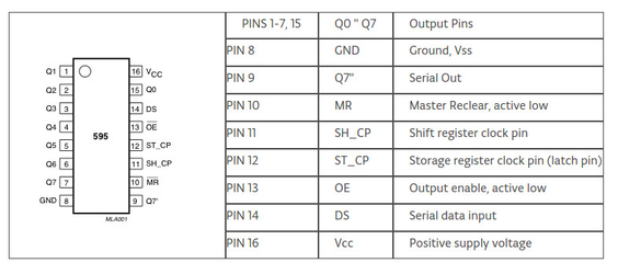
Figure 1 - chip pines Scheme 74HC595.
1. Turning it on
Make the following connections:
- GND (pin 8) to ground,
- Vcc (pin 16) to 5V
- OE (pin 13) to ground
- MR (pin 10) to 5V
This set up makes all of the output pins active and addressable all the time. The one flaw of this set up is that you end up with the lights turning on to their last state or something arbitrary every time you first power up the circuit before the program starts to run. You can get around this by controlling the MR and OE pins from your Arduino board too, but this way will work and leave you with more open pins.
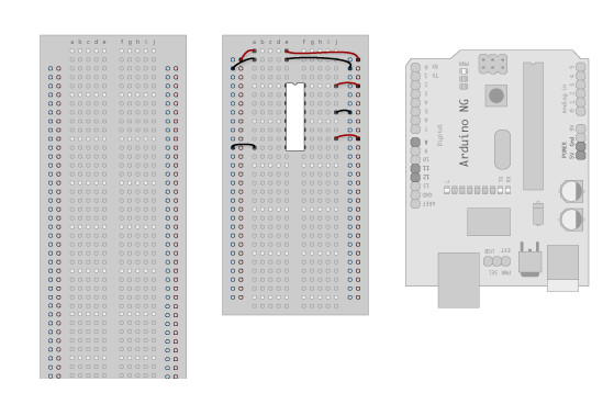
Figure 2 - Wiring diagram of the power supply pins and ground.
2. Connect to Arduino
- DS (pin 14) to Ardunio DigitalPin 11 (blue wire)
- SH_CP (pin 11) to to Ardunio DigitalPin 12 (yellow wire)
- ST_CP (pin 12) to Ardunio DigitalPin 8 (green wire)
From now on those will be refered to as the dataPin, the clockPin and the latchPin respectively. Notice the 0.1"f capacitor on the latchPin, if you have some flicker when the latch pin pulses you can use a capacitor to even it out
on the latchPin, if you have some flicker when the latch pin pulses you can use a capacitor to even it out.
3. Add 8 LEDs.
In this case you should connect the cathode (short pin) of each LED to a common ground, and the anode (long pin) of each LED to its respective shift register output pin. Using the shift register to supply power like this is called sourcing current. Some shift registers can't source current, they can only do what is called sinking current. If you have one of those it means you will have to flip the direction of the LEDs, putting the anodes directly to power and the cathodes (ground pins) to the shift register outputs. You should check the your specific datasheet if you aren"t using a 595 series chip. Don"t forget to add a 220-ohm resistor in series to protect the LEDs from being overloaded.
Figure 4 - Wiring diagram of output pins with the LEDs.
Figure 5 - Circuit Diagram.
5. Add a second shift register.
In this example you'll add a second shift register, doubling the number of output pins you have while still using the same number of pins from the Arduino. Starting from the previous example, you should put a second shift register on the board. It should have the same leads to power and ground.
Figure 6 - Connecting power pins and ground of second registered.
6. Connect the 2 registers.
Two of these connections simply extend the same clock and latch signal from the Arduino to the second shift register (yellow and green wires). The blue wire is going from the serial out pin (pin 9) of the first shift register to the serial data input (pin 14) of the second register.
Figure 7 - Two registers Liaison cascaded.
7. Add a second set of LEDs.
In this case I added green ones so when reading the code it is clear which byte is going to which set of LEDs.
Figure 8 - Expanding eight leds.